The Skittle* Detector**:
A project that determines the color of a skittle, lights a matching LED, and places a count in the appropriate bin.
The purpose of this experiment is to electronically establish the color of a Skittle candy, and count the number of each color detected over a space of time. The skittle is slid into a box where it is uniformly illuminated; the reflected light is detected and sent to the circuit boards where the signal is decoded to establish the color. Components used to accomplish this include: phototransistors, gels, posterboard, op amps, decade counters, pulse generators and 7-segment LED displays. The device was found to be 100% accurate over a period of 3 hours.
Theory
The theory behind this device deals with the reflection, absorption, and transmission of light. White light contains all visible wavelengths; many of these wavelengths will be absorbed by the Skittle, and certain ones reflected very strongly. Each phototransistor receives this reflected light through a filter, thus dealing with only a certain bandwidth in the visible. When strongly reflected wavelengths are transmitted easily through the gel, it results in a high voltage potential being fed into the circuitry board. If highly reflected wavelengths are transmitted poorly through a gel, it results in a lower voltage potential than in the prior case.
Powering the LEDs
Fig.3: At the top of board #12 you see the signal coming from the box, and the voltage divider circuit for the LEDs. There is a follower between the LEDs and the voltage divider, so that if the LEDs changed temperature (which they did), it wouldn't effect the input current and voltage.
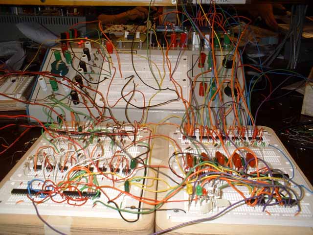
Figure 1. This is most of the circuitry for the color detector.
The Box
In Fig. 2 you see the skittles and the detector box. (Black with white tape.) The skittles are dropped into a paddle that is then slid into the box. Each skittle is illuminated from the sides by two white LEDs. The reflected light then is transmitted through four color gels and into phototransistors on the top of the box. Four unique voltage signals are thereby transmitted to the main circuit board. This signature is analyzed to determine the color of the skittle. The color gels are green, orange, clear and red. Purple, yellow and pink gels did not provide enough contrast. We had to be very careful when aligning the lights so that the detectors recieved the most reflected light and the least amount of direct light. It worked amazingly well for cardboard.
Amplifier and Comparator
The signal from each phototransistor was greatly amplified in order to create a spread of values from 0 to -12V. The purpose is to separate the measurements from the different phototransistors so that there are large enough gaps to create a reliable truth table. Many measurements are taken to establish where gaps fall. Threshold voltages are chosen in the larger gaps in the data table in order to minimize error in final color determination. Luckily, not all of the truth table is necessary, making this experiment much easier than it could have been. Also, due to this flexibility, Skittles can be placed in either the 'S' up or 'S' down position with equal accuracy.
Voltage values above the threshold would be railed to +12V, and voltages below to -12V. This was accomplished with a comparator. The threshold voltage was created by a voltage divider, and fed into V+ on the op amp. The amplifier output was set to V-. The output is railed as a result of the second Golden Rule of Op Amps:the output attempts to do whatever is necessary to make the voltage difference between the two inputs zero.
The signal is then prepped in two ways before being sent into the logic circuitry. First, values of +/- 12V are converted to +/- 5V. Second, there is a feedback effect from the logic chips, so the signal is fed into a follower before going into the logic circuitry.
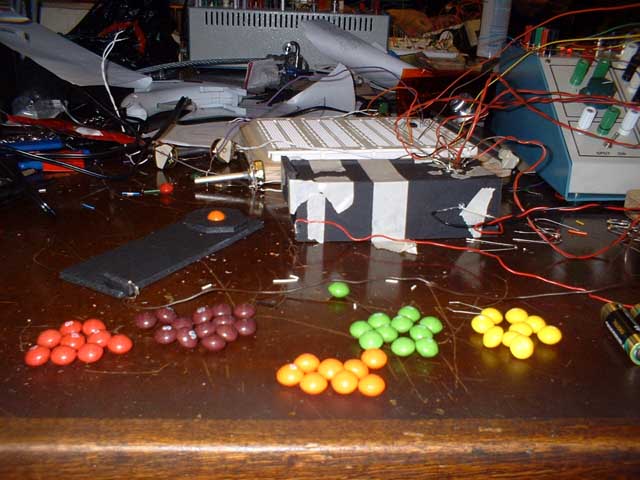
Figure 2.
Color Logic
Logic components include NAND gates on a 7400 chip and inverters on the 7404 chip.
The Switch and Switch logic
A switch is added to take the measurement at a certain instant in order to "freeze" the detected value of the skittle. This was done so that you can see the LED light up.
The switch is normally set to +5V. When the skittle is set in place, the signal is grounded, split five ways, inverted and sent into a NAND gate with one of the "high" outputs from the color logic. The output of each NAND is split. It is used to trigger a 555 operating in monostable mode, and also inverted in order to light up an LED the same color as the skittle. The 555 set in monostable mode is set to debounce our switch. A flip-flop wouldn't work because the switch is not of the SPDT type.
(Initially it was a toss up as to whether it was better to use a peak detector, or to add a mechanical swith that was triggered when the paddle slid in and out. The peak detector was built, but since the color logic relied on purple and green skittles having a low signal, the peak detector would always read purple- there was no peak to detect. Because the accuracy of color determination was high at this point, there was no reason to muck with a good thing. We put in the switch.)
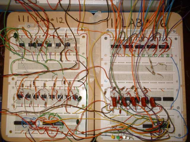
Figure 3.
Decade Counter and Display
A decade counter is made using a 7490 chip. The output of the 555 was connected to Input A of the chip. Input B was connected to Qa to put the chip in counting mode. RO(1), RO(2),R9(1), and R9(2) are set to low according to the Reset/Count Function Table in the specifications of the chip. Supplied in the Lab are 7-segment LED displays (FND357) already hardwired to a 9368, a 7-segment decoder driver chip. The 9368 takes the output from the 7490 and converts in into proper driving voltages fot the FND357. Displaying the counter was just a matter of powering the FND357 and 9368, and connecting the outputs of the 7490 to the inputs of the 9368.
My wonderful lab partner, Brian, and myself.
Conclusions
- Running the LEDs for a long time slowly heats them up, changing their luminosity. The signal from the LEDs is amplified such a large amount that a tiny change in light level affects the amplifier output.
- The LEDs should not be powered separately. The phototransistors are set in a diamond configuration. If one LED experiences a change in light intensity, the closer phototransistors are effected differently than the ones further away. This changes the truth table, resulting in counting errors.
- The gain of the filtered phototransistors shouls be made dependent on the white, creating a self-adjusting truth table. Ideally, the output ratios of the amplifiers would be locked; the threshhold voltages would be set only in relation to each other.
The troublesome Brian-detector, and Mo laughing.